二、Product characteristics
◆ Modular design, high integration degree, stable and reliable performance
◆ Provide 30 slots to support FXS / FXO, magnet, hotline and other audio interfaces
◆ Equipment capacity: 30-way FXS / FXO / magnet phone
◆ Support caller ID
◆ Group route interface: 1 route E 1
◆ Perfect status display, easy for maintenance and management
三、qualification
◆ E1 interface
Interface code type: HDB 3 code
Line rate: 2.048 Mbp / s ± 50 ppm
Interface impedance: 75 Ω / non-equilibrium, 120 Ω / equilibrium
Physical Interface: BNC (75 Ω) / RJ 45 (120 Ω)
Standard: ITU-TG. 703, G.704
Jitter characteristics: meet G.704 and G.823
◆ Magnetic stone interface
Impedance: 6 00 Ω
Audio range: 300-3,400 Hz
Compression rate: A law in ITUG. 711
Echo loss: the ratio is below 18 db
Physical interface: RJ 45
◆ The RS232 interface
Aynchronous RS232 data
Physical interface: RJ 45
Rate: 300~19200B / S
◆ Voice encoding and signaling method
16 with signaling in accordance with ITU-TG. 732
A rate PCM encoding, 64 Kb / S per talk lane, according to ITU-TG. 711
◆ supply electricity
-48V DC (-36~ -72V) or 220V AC (165-265 V) is optional
Power consumption of the whole machine: less than 30W
◆ physical construction
Length * width * height: 482 * 190 * 44 (mm)
四、direction for use
4.1 Description of equipment composition
As shown in the figure below, the equipment is composed of power supply, motherboard, etc. There are 30 slots on the motherboard, which can be inserted into FXO / FXS / magnet, RS232, hotline and other business cards.

4.2 The front panel instructions

- switch declaration
ON: Power is on.
OFF: Power-off.
2, the alarm indicator light instructions
AIS: Frame lost step alarm, when the local device frame lost step, the red light is on.
LOS: Red light is on when the E1 signal is lost.
RA: Bureau alarm. The red light is on when the opposite-end device frame loses out.
2M: E1 input indication. Corresponding green indication when the E1 input signal is normal
The light is on; the corresponding green indicator is off.
O / S: O local terminal work indicator, S remote terminal work indicator.
1~30: Road pickup / data receiving indication. For FXS / FXO, the corresponding path
The indicator light, hang up out. For RS232 data, when the data is receiving or sending data, the indicator light of the corresponding road is always on, and when there is neither receiving or sending data, the indicator light of the corresponding road is extinguished.
RUN: blinking during normal operation.
PW: Power supply indicator light, light on when normal (green).
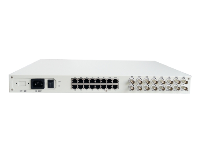
4.3 Description of the rear panel
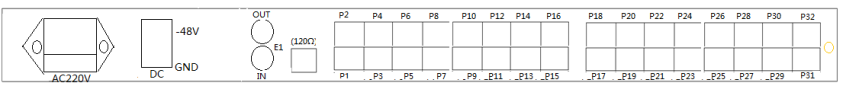
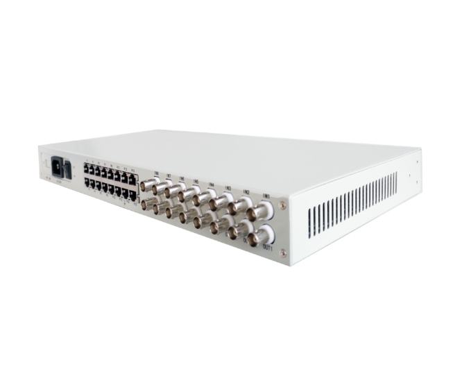
P1~30: The RJ 45 interface. See Table 3 for the pin arrangement of 30-channel voice / data access port and RJ 45 interface
E 1 IN / OUT: The BNC interface. OUT is the output and INis the input.
120 Ω: RJ 45 interface. The 120 Ω (Balanced) E1 access port.
A C220V: 220V power supply access port
-48V DC: -48V DC power access port, GND is the power source.
44 Equipment opening instructions
No setup is required when the device is enabled. It should be noted that the equipment is divided into bureau and household end. When the equipment is installed, pay attention to check the identification on the equipment. The voice interface of the terminal device connects to the user line of the switch, and the voice interface of the terminal device connects to the telephone.
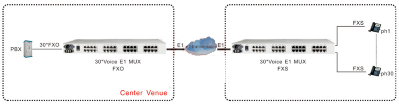
五、Typical application
addendum
1.FXO / FXS / magnet telephone pin arrangement
| RJ45 pin | Signal instructions |
| 1 | |
| 2 | |
| 3 | |
| 4 | TIP |
| 5 | RING |
| 6 | |
| 7 | |
| 8 |
2.E1 (120 euro) RJ 45 pin arrangement
| RJ45 pin | Signal instructions | Signal flow |
| 1 | IN+ | import |
| 2 | IN- | import |
| 3 | ||
| 4 | OUT+ | output |
| 5 | OUT- | output |
| 6 | ||
| 7 | ||
| 8 |